
Screw lifting clamps
Screw Lifting Clamps
Choose a Configuration
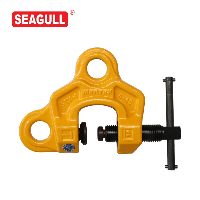
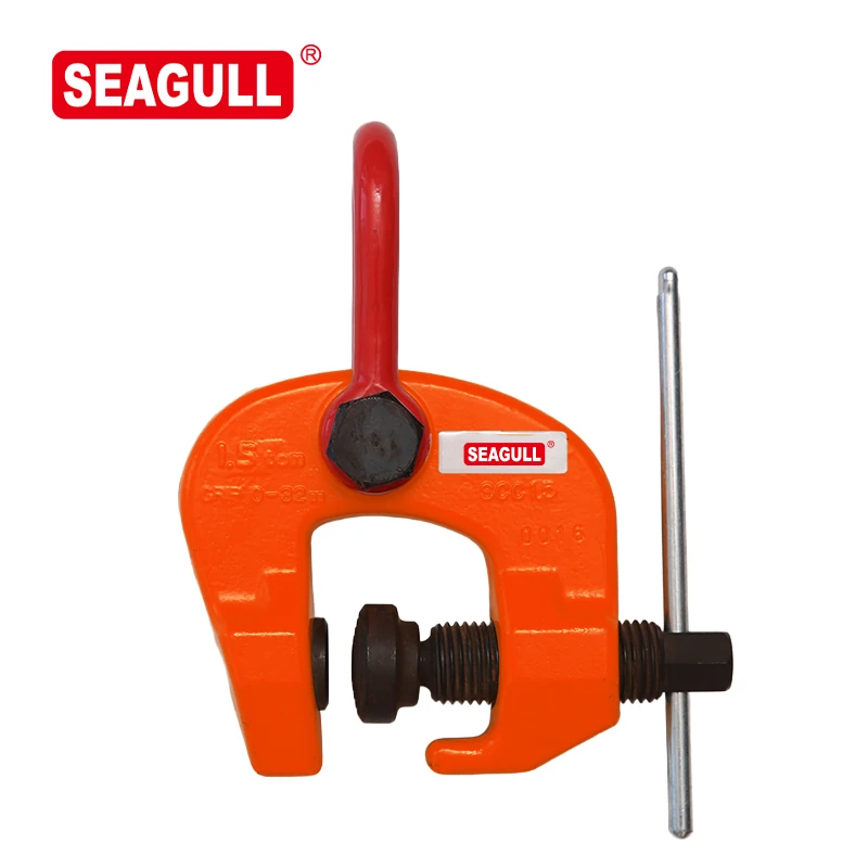
STB and STC use screw-adjusted gripping arrangements for workpiece handling. Compare the suspension connection and screw-cam structure with the workpiece shape, grip thickness, and intended load direction.
Products
Compare the Structures
| Series | Documented arrangement | Model information |
|---|---|---|
| STB | Two suspension holes and a screw-cam gripping arrangement | Review STB screw clamps |
| STC | A movable cam on the threaded spindle and a lifting-eye connection | Review STC screw-cam clamps |
STB-1 and STB-2 list a 0–40 mm clamp range. STB-3.2 lists 5–40 mm. Review the specific series data for the workpiece and load configuration.
Define the Contact and Load Direction
Include the material, shape, thickness at the grip, and surface condition. Supply a sketch showing the intended attachment and load direction. The presence of more than one suspension hole does not by itself establish the allowable load in every direction.
Product Applications
For steel component fitting or alignment, describe the component geometry and the force or load to be applied. If a lever hoist is part of the arrangement, include its connection and the proposed load path.
Request the Screw Clamp Configuration
Send the preferred series, workpiece drawing, load, grip thickness, and attachment layout. Add quantity and destination.