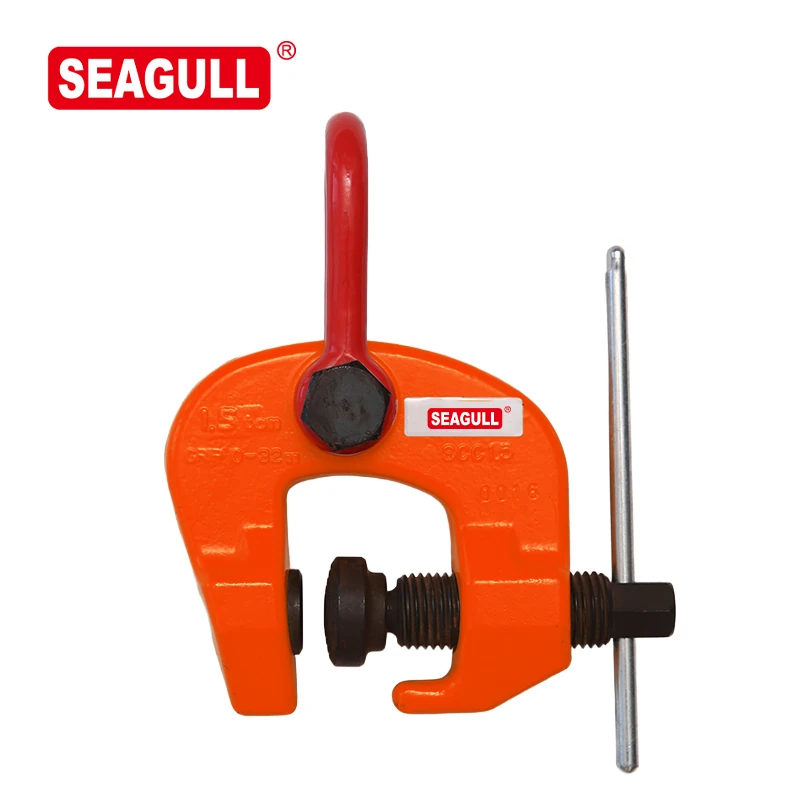
Screw and Cam Contact
The screw applies the initial clamping force through the cam arrangement. Include the contact thickness, surface, and material with the proposed load direction when requesting a configuration.

STB uses a screw-cam gripping arrangement with two suspension holes. STB-1 and STB-2 list a 0–40 mm clamp range; STB-3.2 lists 5–40 mm.
The screw applies the initial clamping force through the cam arrangement. Include the contact thickness, surface, and material with the proposed load direction when requesting a configuration.
The two-hole body provides different connection locations to review. Specify which connection and load path the application requires so the appropriate rated configuration can be confirmed.
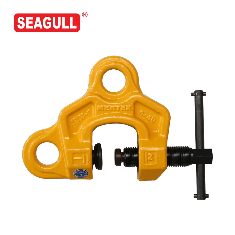
| Product code | Model | Catalog capacity designation (Ton) | Clamp range A (mm) | Catalog minimum tightening torque |
|---|---|---|---|---|
| 60801 | STB-1 | 1 | 0-40 | 25 N·m |
| 60802 | STB-2 | 2 | 0-40 | 25 N·m |
| 60803 | STB-3.2 | 3.2 | 5-40 | 25 N·m |
Ton is the catalog capacity designation. Include the required load in kilograms or pounds for capacity matching. Use the selected model’s instructions to confirm tightening requirements and permitted load directions.
For steel component fitting or clamping, send the workpiece section and intended movement. Include the force or load to be applied and the connection layout, especially where the clamp forms part of a hoist arrangement.
Send the model code, load, gripping thickness, workpiece drawing, and intended attachment. Add quantity and destination.
For a product quote, include the load and unit, lift height, quantity, and electrical supply where relevant. For distribution or integration, describe the product range and market you work with. For product information or support, identify the model and describe your question.
Fields marked * are required.
This form is not connected. Please email your inquiry to info@seagullhoist.com.